Relays and Solenoids
A simple example of using relays and solenoids with water sensors to automate keeping my aquarium topped off with water.
Moving Water with Relays and Solenoids
This is the first section of the series “Krill and the Movement of Water”, where I start with incoming city tap water and cover how it makes its way from place to place using Krill.
The series will cover:
- Water coming into the house from the city and using a water sensor to detect when levels are low and need to be topped off.
- Adding leak sensors using logic gates.
- Using a relay and pump to pull water from the aquarium to feed my aquaponics system and keep my pet tortoise’s jacuzzi full of water.
- Using Atlas Scientific sensors to route water high in conductivity to my aquaponics system.
- Building a CO2 reactor for my planted aquarium and using a relay to control the CO2 solenoid valve based on the color of the CO2 drop checker.
Below is the big water control project enclosure where you can see the Raspberry Pi, relays, solenoids, and other components.
I love working with Reverse Osmosis (RO) parts because they move water in low volumes while under pressure, and there are tons of parts and connectors available.
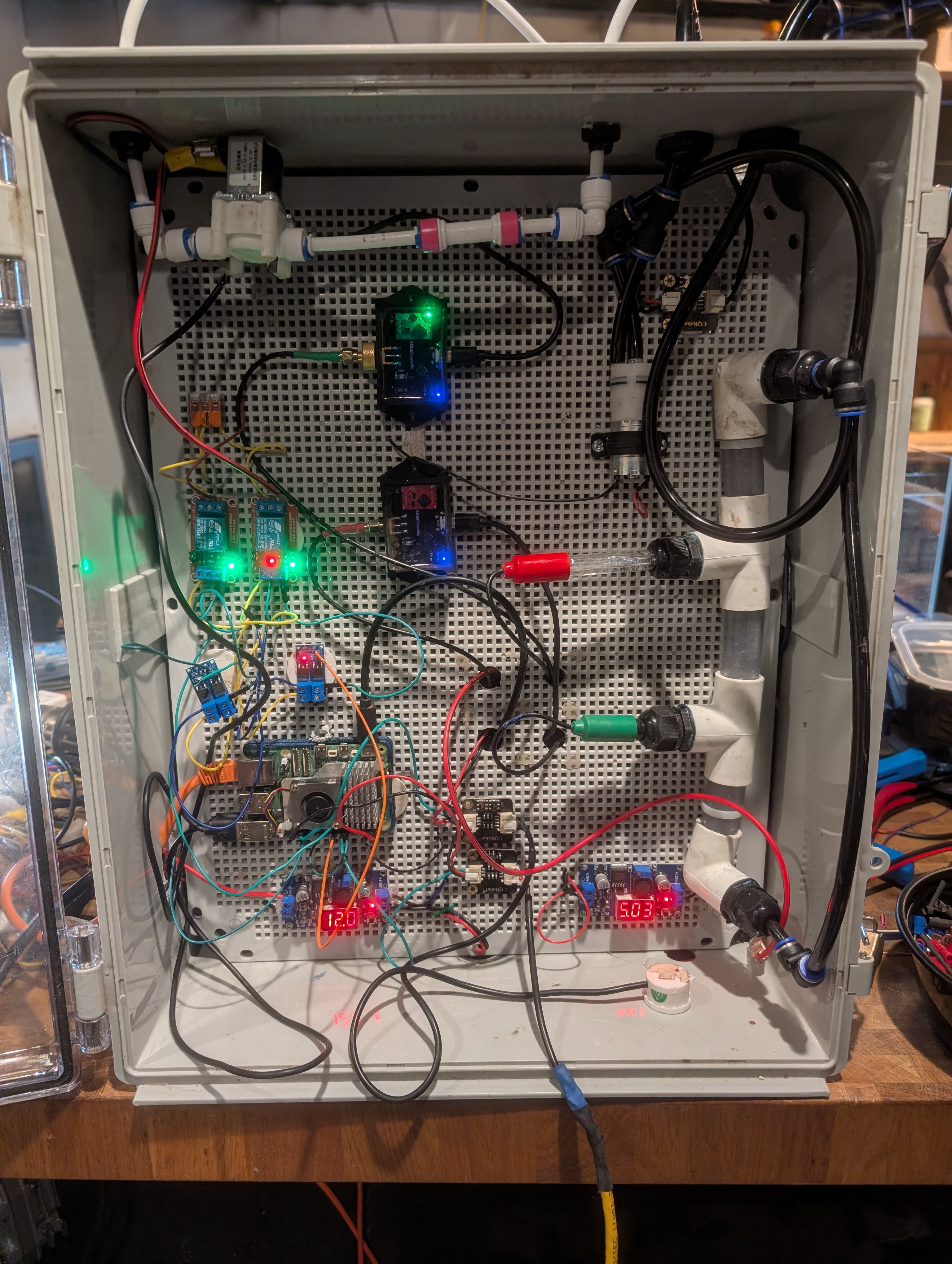
At the top is a 12V solenoid valve that is NC (Normally Closed), so it won’t open in the event of a power failure. Below that is a 12V relay used to control the solenoid valve. The relay is controlled by the Raspberry Pi and can be turned on or off based on the water level detected by the water sensor.
Connected to the Pi on a GPIO pin configured for output is a MOSFET Trigger Switch, which takes the 3.3V signal from the Pi and allows it to control the 12V power to the solenoid valve. This is necessary because the Pi cannot directly power the solenoid valve due to its voltage and current requirements.
The MOSFET switches a 12V relay on and off, which in turn controls the solenoid valve. When the relay is activated, it allows 12V power to flow to the solenoid valve, opening it and letting water flow through. When the relay is deactivated, it cuts power to the solenoid valve, closing it and stopping the flow of water.
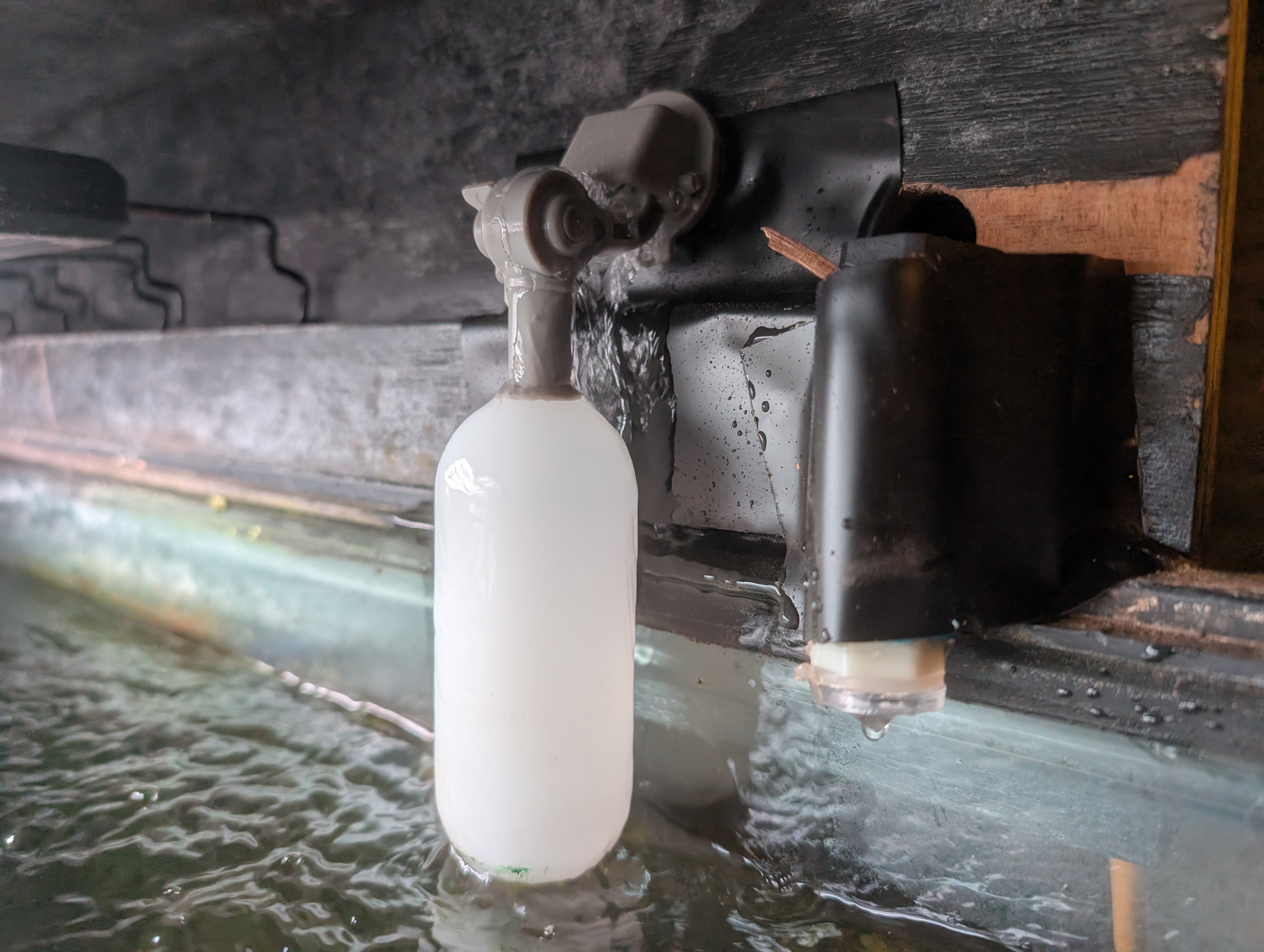
Lastly, I use a contact water sensor to detect the water level. When the water level is low, the sensor triggers the relay to open the solenoid valve and allow water to flow in. Once the sensor detects that the water level is sufficient, it triggers the relay to close the solenoid valve and stop the flow. The float is there for extra safety.
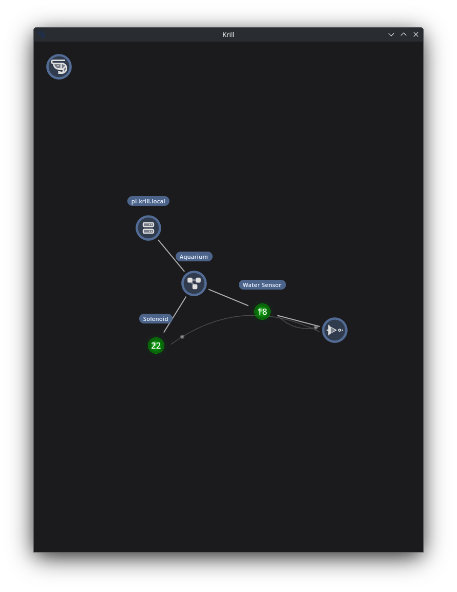
Configuring Krill
The Raspberry Pi in the enclosure is running Krill Server and is configured with a simple logic gate to control the relay based on the water sensor input.
Logic gates are a powerful way of working with digital signals (on/off, true/false, 1/0, etc.), and Krill lets you combine them in all sorts of ways to create complex automation. In this case, we have a simple NOT gate where if the water sensor is on (touching water) the water is off.
Here, I set up two GPIO pins: one for input from the water sensor and one for output to drive the relay and solenoid.
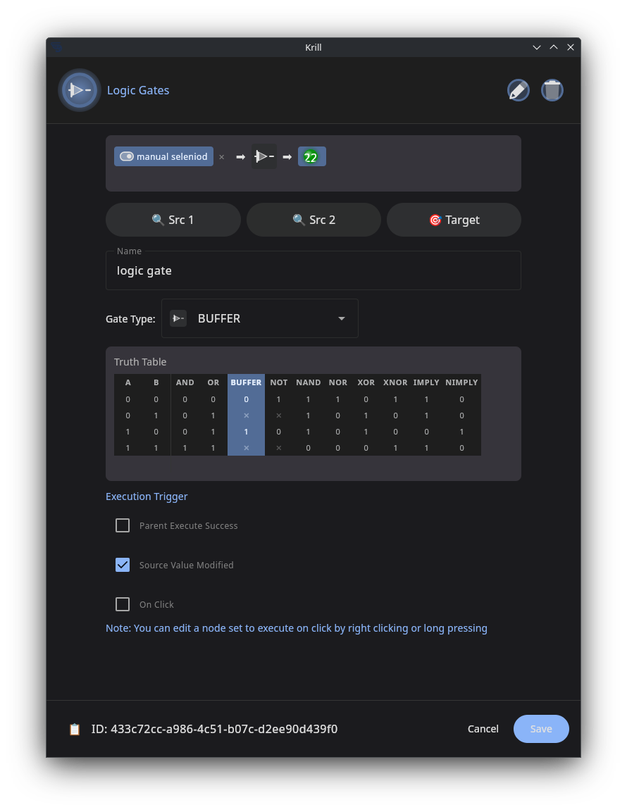
While I’ll cover more complex systems—like adding a leak detector using a NAND gate—in a future post, this simple setup is a great way to get started with controlling water flow using Krill and relays/solenoids.
I simply have a NOT gate where, if the water sensor is triggered (meaning the water level is low), it outputs a true signal to the relay to open the solenoid valve and allow water to flow in. Once the water level is sufficient, the sensor is no longer triggered, and the NOT gate outputs a false signal, causing the relay to deactivate and close the solenoid valve.
Keep Krill’in it!